The Amlogic USB Burning Tool (also known as the Amlogic Flash Tool) is the original desktop utility engineered specifically for flashing stock firmware images onto devices powered by Amlogic processors. This chipset family drives millions of Android TV boxes, OTT media streaming players, smart set-top boxes (STBs), and open-source development hardware modules globally.
Whether you are upgrading to a customized Android interface, flashing a fresh stock operating system, or reviving a completely non-responsive or bricked TV box showing a frozen boot logo, this program serves as your primary PC workstation to push low-level data blocks cleanly.
📥 Direct Download Section (All Stable Builds)
Get the original, clean installation setup wizards from our high-speed direct repository below.
| Software Engine Build Name | Version Type | Direct Download Link |
| Amlogic USB Burning Tool v3.1.8 | Modern UI & SOC Setup | 📂 Download Amlogic Tool v3.1.8 |
| Amlogic USB Burning Tool v2.1.6 | Recommended for Older SOCs | 📂 Download Amlogic Tool v2.1.6 |
Technical Specifications & Vital Rules:
-
File Structure: Official Windows Installer Wizard Setup.
-
Supported OS: Windows 7, 8, 10, 11 (32-bit & 64-bit).
-
Firmware Package Compatibility: Compiled
.imgimage profiles strictly. (Do not load standard recovery.zipOTA upgrade archives into this tool). -
Power Requirement: Ensure your device retains at least 50% power charge or keep its dedicated DC power supply hooked up during execution to avoid accidental cutoff damage.
-
Data Erasure Warning: Flashing system configurations overwrites local flash directories. This process will permanently erase all stored application data, accounts, and system variables on your hardware.
Key Benefits of the Amlogic Burning Tool
-
Comprehensive Driver Autopack: The installer bundle includes integrated Worldcup and specialized processor connectivity drivers. You do not have to manually configure third-party endpoint filters to trace your hardware state.
-
Low-Level Partition Extraction: Features integrated memory wipers designed to handle structural block formatting, allowing clean wipes of broken bootloader code zones.
-
Direct Image Integrity Verification: Automatically scans and validates custom or stock firmware checksum hashes locally before sending them down the wire, protecting devices from corrupt data builds.
How to Install Amlogic USB Burning Tool
-
Download your chosen version archive (v3.1.8 or legacy v2.1.6) from our direct download block table above.
-
Extract the compressed ZIP folder anywhere onto your local desktop path directory using WinRAR or 7-Zip.
-
Open the output folder path, locate
Install_Wizard.exe(or the matching version setup installer file), right-click it, and click Run as Administrator. -
Accept the License Agreement conditions and click Next sequentially.
-
During the progression track, a primary secondary prompt layer from Windows Security will populate asking to flash structural device drivers. Click Install / Allow to finalize the driver mapping rules completely.
How to Flash Firmware via Amlogic USB Burning Tool
Step 1: Initialize the Flashing Dashboard Terminal
-
Double-click the newly generated Amlogic Burning Tool desktop application shortcut path to open the primary dashboard pane environment.
-
Language Toggle Note: If the interface layout initializes in Chinese characters, navigate to the top-left structural option header row, click the second menu tab from the left, and choose English to swap text profiles.
Step 2: Import Your Official Firmware File
-
Move your mouse to the upper file control layout rows and click on File ➔ Import Image.
-
A Windows Explorer navigation box path will populate on your display layout.
-
Browse your local files to highlight your unzipped stock
.imgfirmware package built specifically for your exact device box model configuration and click Open. -
Leave the interface running quietly for a brief moment while the application log processes the verification checks.
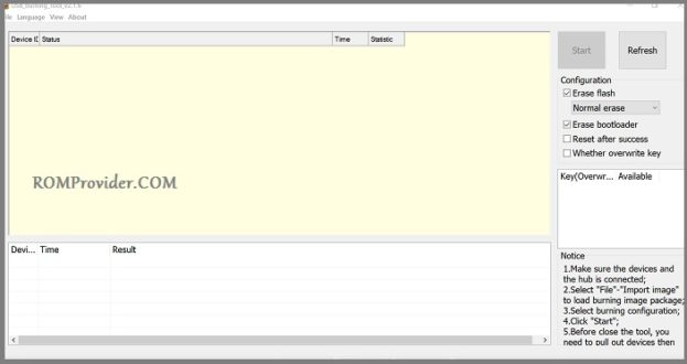
Step 3: Put the Software into Active Listen Standby
-
Check the configurations configuration panel blocks sitting on the right sidebar row interface. Ensure your baseline settings map your desired format paths (Standard configurations use Normal Erase settings).
-
Click on the large Start action prompt button positioned at the top right header pane layout. The application layout grid fields shift directly into active tracking standby.
Step 4: Trigger the Connection via Recovery Boot Mode
To let your PC intercept the raw processor lines directly over a basic male-to-male USB configuration patch cord, you must bypass your device’s primary operating system boot paths:
-
Turn off your Amlogic Android TV box completely.
-
Locate the device’s hidden mechanical restore button. (On the vast majority of Android STB streaming units, this tiny switch sits hidden deep inside the physical Audio AV output jack hole interface or secondary pin ports).
-
Compress and hold down that restore switch firmly using a non-conductive toothpick, paperclip, or matching technical pin tool.
-
While keeping that hardware button compressed firmly, link the device to your PC’s native USB port with your data wire. (Tip: Use the specialized USB host port channel located closest to the main DC power input supply jack configuration if your hardware displays detection failures).
-
The main software dashboard row fields will instantly track the port registration signature line and output a green string text banner reading “Connect Success”. You can now pull your pin out and release the switch.
Step 5: Monitor the Transfer Success State
-
Flashing Track Loop: The application engine will automatically push configuration loaders and launch a tracking progress bar percentage monitor. Keep the data cord line completely untouched during the sequence.
-
Completion Check: Once the visual status metrics reach 100%, the progress track block banner will change entirely to solid green and log a text confirmation reading “Burning Successful”.
-
Rebooting Setup: Click the main Stop action execution button inside the panel configuration headers, unplug the device patch cable, hook it up to your television monitor interface, and power it back on!